![]()
Following on from my intial thoughts on the BBC Micro:bit the other day, I thought I’d have a play with the electronic connectivity abilities of the device. The Kitronik Inventors’ Kit has a little booklet with 10 project ideas so I picked a suitably complicated one and wrote the code for it myself. Then I got carried away and took it a bit further.
LED The Way
The project I picked is a simple LED driver project with the slightly more exciting aspect of using a tri-colour RGB LED. These devices are actually 3 LEDs in one package with 3 anodes and a common cathode. Driving it is as easy as driving 3 independent LEDs.
The circuit has three buttons and the aforementioned RGB LED. The buttons are wired to the Micro:bit such that pressing them will increase the level of one of the three colours in small increments. Using different colour levels, different composite colours can be created.
The schematic for the circuit is as follows:
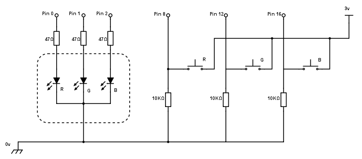
Not too complicated at all, and making good use of the analogue output capablities of the Micro:bit. Analogue input will be the subject of a future project.
Code me up
The initial version of the code sticks very closely to the project brief, allowing the buttons to increment the different colour values in small increments. The increments and limits were found by trial and error; it seems that although the maximum output value of 1023 is possible, anything over 250 resulted in negligible difference in light output.
Capping at 250 and with a step size of 5 should allow pretty smooth increases in output by holding a button down. I also found that the three colours have different responses to the same input. The blue tends to overwhelm the red and green, and the yellow I made with just red and green had a distinctly green hue. Maybe using variable resistors to calibrate the colour response would work?
    from microbit import *

    MAX=250
    STEP=5

    def pin_pressed(p):
        def pressed():
            return p.read_digital() == 1
        return pressed

    red_pressed = pin_pressed(pin8)
    green_pressed = pin_pressed(pin12)
    blue_pressed = pin_pressed(pin16)

    def update_pin(p):
        def update(v):
            v = min(MAX, max(0, v))
            p.write_analog(v)
        return update

    update_red = update_pin(pin0)
    update_green = update_pin(pin1)
    update_blue = update_pin(pin2)

    def increment(v):
        return (v + STEP) % MAX

    red = 0
    green = 0
    blue = 0

    while True:
        sleep(100)

        do_update = False
        if red_pressed():
            red = increment(red)
            update_red(red)

        if green_pressed():
            green = increment(green)
            update_blue(blue)

        if blue_pressed():
            blue = increment(blue)
            update_green(green)
Doing a spot of the old first class function manipulation there. The functions
to update specific colours are closures generated by the update_pin()
function, and similarly the functions to get the state of the buttons are
closures generated by the pin_pressed() function. Means that I have
semantically useful function names, rather than generic parameterised functions.
There’s probably a nicer way to handle the update calculation and I might yet get round to it. Note that the increment function makes the value wrap to 0 as it hits the 250 maximum.
Here is the finished circuit:
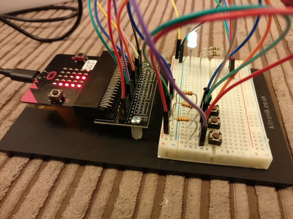
Getting carried away
You’ll probably notice that in that photo there is … something … on the screen. That is the next bit where I get carried away. I decided that I wanted a couple of extra functions; first, a graphical representation of the levels of each LED and second, a way to quickly reset the state.
Here is my updated version:
    from microbit import *

    MAX=250
    STEP=5

    def pin_pressed(p):
        def pressed():
            return p.read_digital() == 1
        return pressed

    red_pressed = pin_pressed(pin8)
    green_pressed = pin_pressed(pin12)
    blue_pressed = pin_pressed(pin16)
    max_pressed = button_a.was_pressed
    clear_pressed = button_b.was_pressed

    def update_pin(p):
        def update(v):
            v = min(MAX, max(0, v))
            p.write_analog(v)
        return update

    update_red = update_pin(pin0)
    update_green = update_pin(pin1)
    update_blue = update_pin(pin2)

    def update_display(r, g, b):
        bucket = MAX // 5
        def update_column(x, v):
            for y in range(4, -1, -1):
                if v == 0:
                    display.set_pixel(x, y, 0)
                elif v < bucket:
                    display.set_pixel(x, y, v * 9 // bucket)
                    v = 0
                else:
                    display.set_pixel(x, y, 9)
                    v = v - bucket
        update_column(0, r)
        update_column(2, g)
        update_column(4, b)

    def update(r, g, b):
        update_red(r)
        update_blue(b)
        update_green(g)
        update_display(r, g, b)

    def increment(v):
        return (v + STEP) % MAX

    red = 0
    green = 0
    blue = 0

    while True:
        sleep(100)

        do_update = False
        if red_pressed():
            red = increment(red)
            do_update = True

        if green_pressed():
            green = increment(green)
            do_update = True

        if blue_pressed():
            blue = increment(blue)
            do_update = True

        if max_pressed():
            red = MAX
            green = MAX
            blue = MAX
            do_update = True

        if clear_pressed():
            red = 0
            green = 0
            blue = 0
            do_update = True

        if do_update:
            update(red, green, blue)
Now I use a flag to determine when to update everything and do it all in one go via the update function. Again, there’s probably a nicer way to do the checks but this is readable insofar as each bit is a logical chunk of code.
The result is that columns 0, 2 and 4 of the display are used to display the R, G and B levels respectively. It uses the dimmable pixels feature to make the topmost light of each column get brighter as the level increases in steps too small to represent every change on its own pixel. Working within the 5x5 limit causes some interesting thought processes but it works really well.
The max_pressed() and clear_pressed() functions are driven by the built-in
buttons A and B. Pressing A sets all colours to MAX, and pressing B sets all
colours to 0, effectively turning off the display and the LED.
Onward and upward
While I’ve been playing with this there has been a parallel thread of learning going on. So while I’ve built a traffic light simulator with pelican crossing, we also have a Tama-doggy, a light level detector and, by the end of the day, a musical instrument made of three bananas.
Watch this space!